Arduino Ping Sensor With Visuino Software
In this coding sample I will show you how to code your an Arduino Ping Sensor using Visuino Software. We will go over the building blocks that makes this code simple to use with just few fundumental blocks.
Also i'm assuming that you have an Arduino Board and the ping sensor.

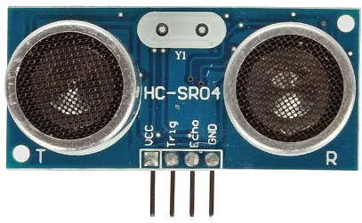
The first building block is the Ultrasonic Ranger

The ping sensor has an Echo pin (which we will connect to digital 2 output), Ping /Trigger pin (which we will connect to digital 3 input) and out pin.
The out pin we will connect to the next building block.
The next building block is the Average Period block

This block will take the output from the ping sensor and sample it. It will output in the end of sample the average value.
This will help with reducing noise from the ping sensor and will give us a more relayable output.
The output of this block will be the distance the ping sensor recoreded. (in my case i'm using cm but you can change the value from the properties panel on the left).
We now need to compare this distance with the 3 values for each LED. values > 60 will turn the green LED; values between 40 & 60 (40 < value < 60) will turn the yellow LED;
finally values between 0 & 40 (0 < value < 40) will turn the red LED.
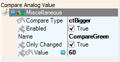
This leads us to the next block which is Compare Analog Value

The compare analog value will take as an Input the output from Average Period Block above and compare it to a constant value.
There is an option to change the compare type of that block in the properties panel on the left side as showing below.

The output of this block will be either true or false (hence analog output).
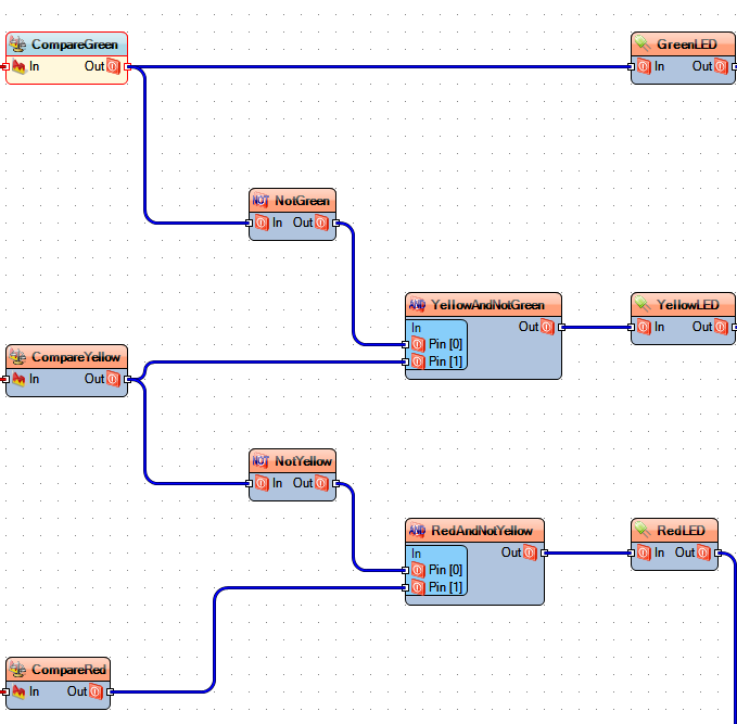
For green value we can conncet it right away to the LED block (see below); however, for yellow and red LEDs we will need to do some gate checks (because we need the values to be between two values)
The logic gates (And & Not) will help us making the decition for the yellow and red. If we think about this as if statements it will be easier to see
else if (value < 60 && value > 40 )
else if (value < 40 && value > 0 )

The last piece of this is to connect the outputs of the gates (or from the green compare) to the LED block, which than we will connect the output of the LED to digital outputs (in my case 5,6,7 for Green, Yellow and Red respectively)

And that is basically it. All you need to do now, is connect your Arduino with the Ping and LEDs to the same pin outs you set in Visuino and click The Arduino icon in Visuino (you can do F9 to send it to Arduino IDE or Ctrl + F9 to upload it to the Arduino )

If you need a guide on how to start with puck check out my Arduino Ping and Visuino
You can download the Visuino Code
